- 您现在的位置:买卖IC网 > Sheet目录1217 > GDBD4410 (IXYS)BOARD EVALUATION IXBD4410/11
�� �
�
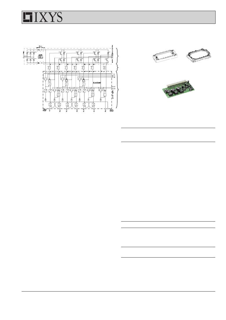
�GDBD� 4410�
�Funtional� Block� Diagram�
�MUBW� module�
�gate� resistors�
�driver� boards�
�Logic� Interfaces�
�Symbol�
�Definitions�
�Ratings�
�Logic� interface� comprises� seven� input� signals� PBM1� to� PBM7:�
�?� PBM1� controls� transistor� T1,� PBM2� controls� transistor� T2;� cross�
�conduction� interlock� prevents� both� transistors� from� being� turned� on�
�v� DD�
�I� in�
�t� p�
�Input� Voltage� (PBM1...7)� -0.5...V� DD� +0.5�
�Input� Current� (PBM1...7)� ±10�
�min.� high/low� pulse� width� for� PBM1/3/5� 1�
�V�
�A�
�μs�
�at� the� same� time.�
�?� PBM3� controls� transistor� T3,� PBM4� controls� transistor� T4;� cross�
�conduction� interlock� prevents� both� transistors� from� being� turned� on�
�at� the� same� time.�
�?� PBM5� controls� transistor� T5,� PBM6� controls� transistor� T6;� cross�
�conduction� interlock� prevents� both� transistors� from� being� turned� on�
�at� the� same� time.�
�?� PBM7� controls� brake� transistor� T7.�
�All� PBM� signals� have� the� following� properties:�
�?�
�?�
�?�
�?�
�They� are� ground� referenced,� i.e.� refer� to� potential� of� minus� DC� link.�
�Logic� 1� turns� the� transistor� on,� logic� 0� turns� it� off.�
�The� signals� are� TTL/CMOS� compatible.�
�A� pull� down� resistor� of� 4,7� k� ?� is� provided� on� board.�
�Further,� an� output� F signal� indicating� fault� status� is� provided,�
�see� section� Protection� Schemes�
�Isolated� Signal� Transmission�
�Symbol�
�Definitions�
�Max.� Ratings�
�In� the� driver� unit� the� high-side� ICs� are� isolated� from� the� low-side�
�L� Gb� /� L� GI�
�maximum� common� mode� dv/dt�
�±50�
�V/ns�
�ICs� by� magnetic� barriers.� There� are� two� magnetic� transmission�
�channels� between� the� low-� and� high-side� ICs� for� bidirectional�
�communication.� One� sends� a� signal� from� the� low-side� IXBD4410�
�IC� up� to� the� high-side� IXBD4411� IC� and� the� other� sends� a� signal�
�back� from� the� high-side� to� the� low-side� IC.� The� signal� that� is� sent�
�Symbol�
�Definitions/Conditions�
�Characteristic� Values�
�min.� typ.� max.�
�up� controls� the� IXBD4411� gate-drive� output.� The� signal� sent�
�d� S�
�creepage� distance� on� board�
�2�
�mm�
�from� the� IXBD4411� back� to� the� IXBD4410� indicates� a� high-side�
�fault� has� occurred� which� is� detected� at� the� IXBD4410� IC.�
�Magnetically� coupled� signal� transmission� leads� to� high� immunity�
�against� disturbances� caused� by� voltage� change� rates� du/dt,�
�which� necessarily� occur� in� power� electronic� phaseleg� circuits.�
�?� 2004� IXYS� All� rights� reserved�
�between� high� &� low� side� potential�
�2-6�
�发布紧急采购,3分钟左右您将得到回复。
相关PDF资料
GH1250
FUSE INDUST 1250A 550V 84X198MM
GMF.3K.085.EANZ
RUBBER BOOT
GPIODM-KPLCD
BOARD DEMO LCD GPIO EXP KEYPAD
GSAP 15-R
FUSE 15A 250VAC AXIAL SLOW
GSB3211311WEU
USB 3.0 DIP B RECP THRU HOLE
GSB343K33HR
USB 3.0 MICRO B RECP SMT
GT-BG230L
ARRESTOR 230VDC HD GASTUBE GLASS
GT-BG350L
ARRESTOR 350VDC HD GASTUBE GLASS
相关代理商/技术参数
GDBE111630-19
制造商:ITT Interconnect Solutions 功能描述:GDBE111630-19 - Bulk
GDBE-25S-A156
制造商:ITT Interconnect Solutions 功能描述:GDBE-25S-A156 - Bulk
GDB-V-1.25A
制造商:Cooper Bussmann 功能描述:Fuse Miniature 1.25A 250V Fast 2-Pin Axial Through Hole Cardboard Carton
GDB-V-1.6A
制造商:Cooper Bussmann 功能描述:
GDB-V-100MA
制造商:Cooper Bussmann 功能描述:
GDB-V-10A
制造商:Cooper Bussmann 功能描述:
GDB-V-125MA
制造商:Cooper Bussmann 功能描述:Fuse Miniature 0.125A 250V Fast 2-Pin Axial Through Hole Cardboard Carton
GDB-V-160MA
制造商:Cooper Bussmann 功能描述:Fuse Miniature 0.16A 250V Fast 2-Pin Axial Through Hole Cardboard Carton